Back to GameBoy Emulation in JavaScript
This is part 8 of an article series on emulation development in JavaScript; ten parts are currently available, and others are expected to follow.
Please note: This article has been updated to remove an incorrect interrupt handling procedure. --12th Nov, 2010
In the previous part, the foundations for simulating a game were laid, with the introduction of sprites. However, one aspect was missing from the emulator: the vertical blanking interrupt. In this part, interrupts as a whole will be introduced, and the blanking interrupt in particular will be implemented; once this has been done, the emulator will run Tetris.
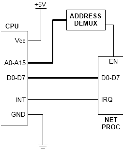
Imagine that you have a computer with a network card, and some software that processes data from the network. From the perspective of the computer, data only comes in every so often, so you need some way for the software to know that new data has arrived. There are two ways for this to happen:
- Polling: The software asks the network card every so often whether new data has arrived. This is a simplistic way of doing things, but has disadvantages:
- The software doesn't know about new data until its periodic check, which means a delay between the data arriving at the computer and it being handled by the software;
- Time has to be taken out on a periodic basis for the checks to be made, taking time away from other work even if no data has arrived;
- If the polling process handles one piece of new data each time it checks, but data is arriving at a faster rate, a backlog of data is created in the network card, and there's potential for some data to be lost;
- If there is no other work to be done, the software still has to check for data, which keeps the computer running at full speed with no work to do.
- Interrupts: The network card informs the software that new data has arrived. This is a more complicated way of receiving data, with more steps involved, but it alleviates all the disadvantages of polling:
- New data can be processed as soon as it arrives, with no delay between arrival and the data being handled;
- The software need only take time to handle data when there's definitely data to be handled, and the processing routines can be called as often as necessary to clear any backlogs;
- If there is no other work to be done, the computer can enter a low-power mode until the network card awakens it for new data.
Interrupts and interrupt handlers
It's obvious that the concept of interrupts is a useful one, but there are both hardware and software requirements for interrupts to work. In hardware terms, the CPU has to temporarily stop execution of what it's doing when an interrupt arrives, and instead begin execution of an interrupt handler (sometimes referred to as an Interrupt Service Routine). In the above scenario, a wire is run between the network card and the CPU, allowing the card to inform the CPU when data has arrived.
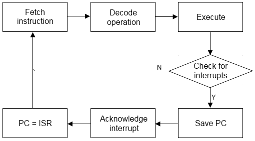
The CPU will check its interrupt inputs at the end of every instruction. If an interrupt signal has been given by some attached peripheral like the network card, steps are taken by the CPU to start the interrupt handler: the CPU will save the location where it left off normal execution, register the fact that the interrupt happened, and jump across to the handler.
In the GameBoy, there are five different interrupt wires, feeding in from the various peripherals. Each one has its own ISR at a different address in memory; the list of interrupts is as follows.
| Interrupt | ISR address (hex) |
|---|---|
| Vertical blank | 0040 |
| LCD status triggers | 0048 |
| Timer overflow | 0050 |
| Serial link | 0058 |
| Joypad press | 0060 |
In the case of the vertical blank, a wire is threaded into the bottom of the LCD; as soon as the GPU has finished scanning all the LCD lines and runs into the bottom of the screen, the interrupt fires and the CPU jumps to 0040, executing the blanking ISR.
Implementation: Interrupt flags
Most CPUs contain a "master flag" for interrupts: they will only be handled by the CPU if this flag is enabled. The Z80 in the GameBoy is no exception, but there are additional registers that deal with the individual interrupts available in the GameBoy. These are memory registers, so they are handled by the memory management unit:
| Register | Location | Notes | Details | ||||||||||||||||||
|---|---|---|---|---|---|---|---|---|---|---|---|---|---|---|---|---|---|---|---|---|---|
| Interrupt enable |
FFFF |
When bits are set, the corresponding interrupt can be triggered |
|
||||||||||||||||||
| Interrupt flags |
FF0F |
When bits are set, an interrupt has happened |
Bits in the same order as FFFF |
Since these are memory registers, their implementation is something for the MMU:
MMU.js: Interrupt flags
MMU = {
    _ie: 0,
    _if: 0,

    rb: function(addr)
    {
	switch(addr & 0xF000)
	{
	    ...
	    case 0xF000:
	        switch(addr & 0x0F00)
		{
		    ...
		    // Zero-page
		    case 0xF00:
		    	if(addr == 0xFFFF)
			{
			    return MMU._ie;
			}
		        else if(addr >= 0xFF80)
			{
			    return MMU._zram[addr & 0x7F];
			}
			else
			{
			    // I/O control handling
			    switch(addr & 0x00F0)
			    {
			    	case 0x00:
				    if(addr == 0xFF0F) return MMU._if;
				    break;
			    	...
			    }
			    return 0;
			}
		}
	}
    },
    ...
};
The Z80's "master enable" switch is, in a similar manner, something for the Z80 implementation. The CPU provides opcodes for software to flick the master enable into either On or Off position, so these will also need to be implemented:
Z80.js: Interrupt master enable
Z80 = {
    _r: {
        ime: 0,
        ...
    },

    reset: function()
    {
        ...
	Z80._r.ime = 1;
    },

    // Disable IME
    DI: function()
    {
    	Z80._r.ime = 0;
	Z80._r.m = 1;
	Z80._r.t = 4;
    },

    // Enable IME
    EI: function()
    {
    	Z80._r.ime = 1;
	Z80._r.m = 1;
	Z80._r.t = 4;
    }
};
Implementation: Interrupt handling
With the interrupt flags in place, the main execution loop can be redeveloped, to fall more in line with the execution path from figure 3. After execution, the interrupt flags need checking to see whether an enabled interrupt has occurred; if it has, its handler can be called.
Z80.js: Vblank interrupt handler
Z80 = {
    _ops: {
	...

        // Start vblank handler (0040h)
        RST40: function()
        {
            // Disable further interrupts
    	    Z80._r.ime = 0;

    	    // Save current SP on the stack
    	    Z80._r.sp -= 2;
    	    MMU.ww(Z80._r.sp, Z80._r.pc);

    	    // Jump to handler
    	    Z80._r.pc = 0x0040;
	    Z80._r.m = 3;
    	    Z80._r.t = 12;
        },

        // Return from interrupt (called by handler)
        RETI: function()
        {
	    // Restore interrupts
	    Z80._r.ime = 1;

	    // Jump to the address on the stack
	    Z80._r.pc = MMU.rw(Z80._r.sp);
	    Z80._r.sp += 2;

	    Z80._r.m = 3;
	    Z80._r.t = 12;
        }
    }
};

while(true)
{
    // Run execute for this instruction
    var op = MMU.rc(Z80._r.pc++);
    Z80._map[op]();
    Z80._r.pc &= 65535;
    Z80._clock.m += Z80._r.m;
    Z80._clock.t += Z80._r.t;
    Z80._r.m = 0;
    Z80._r.t = 0;

    // If IME is on, and some interrupts are enabled in IE, and
    // an interrupt flag is set, handle the interrupt
    if(Z80._r.ime && MMU._ie && MMU._if)
    {
        // Mask off ints that aren't enabled
        var ifired = MMU._ie & MMU._if;

	if(ifired & 0x01)
	{
	    MMU._if &= (255 - 0x01);
	    Z80._ops.RST40();
	}
    }

    Z80._clock.m += Z80._r.m;
    Z80._clock.t += Z80._r.t;
}
Next time: Bigger games
As shown in Figure 1, the emulator has reached a reasonable stage: it's able to emulate a released game in at least some form. It does, however, have the problem of game size. Tetris is a 32kB ROM, and fits perfectly into the "ROM" space in the memory map. Games tend to have larger ROMs than this, and the cartridge follows a process of mapping portions of the ROM into memory. Next time, I'll look at the simplest available form of ROM mapping for the GameBoy, and its implementation on a 64kB game ROM.
Imran Nazar <tf@imrannazar.com>, Nov 2010.