Back to Let's Build a JPEG Decoder
This article is part one of a series exploring the concepts and implementation of JPEG decoding; four parts are currently available, and others are expected to follow.
Build a JPEG decoder? Whatever for, when we have so many of them already?
JPEG is something we all take for granted: most of the Web comprises pictures transmitted as JPEG files, and video files based on JPEG technology. As it turns out, the concepts that lie behind these images span nearly two hundred years of mathematics and computing theory, and going from the raw file to an image takes a bunch of interesting work.
At the core: frequency analysis
In An Introduction to Compression, I looked at the difference between "lossless" and "lossy" compression: the difference between the two methods is that lossless compression preserves all the inherent information of the input, whereas lossy compression throws much of it away. Throwing information away only works when it can be deemed unnecessary for proper handling of the file; this would never be the case for a computer program, for example, where every byte is a statement that must be retained.
Images or videos, and their cousins in the audio world, rely on perception to work out what needs to be thrown away: just as the human ear can only distinguish sounds in a particular region of frequencies, the human eye has a particular resolution and any colour changes that happen within a very short distance are essentially invisible. Resolution can also be thought of as "visual frequency", and can be manipulated in much the same way as sound wave frequency or other kinds of wave.
It follows that a chunk of sound or a piece of an image can be compressed by removing those parts of the frequency range that are outside the human experience: those frequency ranges that we don't care about, without which the essence isn't lost. There are three steps to doing that:
- Transform the sample: Sound waves are changes of sound level through time, and images are changes of colour through two dimensions of space. We need somehow to change these into frequency representations of themselves, through a transformation.
- Band-pass: Once we're in the frequency domain, we need to cut out the section, or band, of frequencies that interests us. The technical term for this is a "band-pass filter".
- Inverse transform: Our newly reduced signal can then be sent backwards through the transformation, resulting in a sound or image that's had its excess information stripped.
The transformation use is derived from the Fourier transform, which takes an integratable mathematical function f(x) and generates an equation f(s) for a frequency spectrum. The Fourier transform only works with continuous ranges of numbers, and extends from negative infinity to positive infinity; this makes it unusable for digital transformations like those we need here. Instead, a discrete version of the Fourier transform is used: the MP3 and JPEG techniques use the discrete cosine transform (DCT) to change a set of data values into an equivalent set of frequencies.
Two examples of the compression process are presented in the following figures: first for a short sound sample.
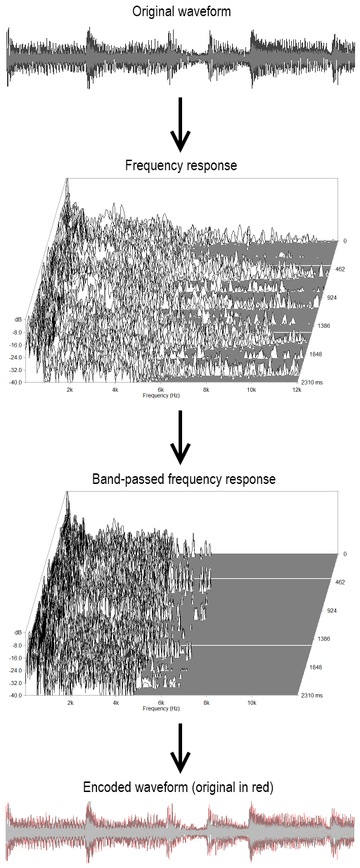
Encoded to 40kbps MPEG audio Layer 3
Frequency analysis courtesy of ARTA for Windows, by Ivo Mateljan
The below figure represents the same process as above, but applied in two dimensions of space as opposed to one of time. It is generally considered inefficient to transform the entire image into a visual frequency domain at once, so the JPEG algorithm transforms blocks of eight pixels square at a time.
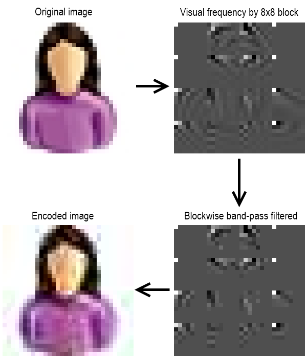
Encoded to JPEG, q=25%
In Figure 2, the right-hand set of images show the DCT and its filtered version. The most important figure in each 8x8 block is the "DC component" in the top-left, which determines the base level for the whole block. Values to the right of this give information as to how often variances happen horizontally, and conversely values below the DC component provide vertical frequency information. It follows that values in the bottom-right of a DCT block describe the highest-fidelity changes in the image, and that filtering consists of drawing a diagonal across each block and retaining the top portion, throwing away the information regarding high-fidelity changes.
Colour spaces and downsampling
JPEG makes use of the fact that the human eye has a maximum resolution when it comes to visual changes. Another feature of the eye is that it is less sensitive to changes in colour than in brightness: the frequency-sensitive "cone" cells of the retina occur at a lower density than the simpler frequency-agnostic "rods", which means a lower visual resolution for colour.
It is possible for images to be further compressed by utilising this information, reducing the amount of information used to encode colour values in relation to brightness. Unfortunately, the traditional additive colour space of red/green/blue used by computer and television displays retains no information about relative brightness and colour saturation; in order to retrieve this information RGB values must be transformed to another colour model.
The JPEG format most commonly uses Y'CbCr colour, where Y' denotes the luminance of a particular pixel, and the Cb and Cr components describe the amount of chrominance on two axes, corresponding to percentages of blue and of red. Transformations from RGB pixel values to Y'CbCr act as a rotation between the cube of all possible RGB values and the cube of possible luminance/chrominance values, as shown in Figure 3.
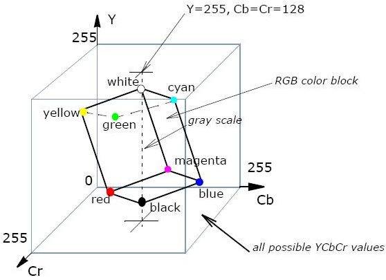
From the Intel Integrated Performance Primitives manual
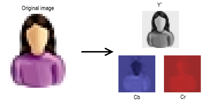
Once transformed to Y'CbCr, the chrominance channels are separated out and can be manipulated. In this case, "downsampling" is employed: the resolution of the colour channels is halved in both dimensions, such that one "block" of colour information covers the equivalent area of four luminance blocks. In Figure 4, the colour channels have been downsampled by this ratio: it can be seen that the Y' channel is the most important for the integrity of the image, and thus its resolution remains high.
For the remainder of this series of articles, bidirectional downsampling of the type shown here will be assumed: most JPEG images on the Web employ this colour compression, so it's useful to explore. Because of the reduction in resolution, the previously mentioned eight-pixel square used by the JPEG algorithm becomes a minimum unit size of 16 pixels square, with four 8x8 luminance blocks accompanying one block for each axis of colour information.
Next time: The file format
JPEG files store additional information alongside the encoded image: lookup tables to be used by the decoding process, comments and resolution information. In part two, I'll take a look at the segments that make up a JPEG file, and how to hold onto some of the information provided for use by the decoding implementation of subsequent parts.
Imran Nazar <tf@imrannazar.com>, Jan 2013.