Back to GameBoy Emulation in JavaScript
This is part 4 of an article series on emulation development in JavaScript; ten parts are currently available, and others are expected to follow.
Previously in this series, the shape of a GameBoy emulator was brought together, and the timings established between the CPU and graphics processor. A canvas has been initialised and is ready for graphics to be drawn by the emulated GameBoy; the GPU emulation now has structure, but is still unable to render graphics to the framebuffer. In order for the emulation to render graphics, the concepts behind GameBoy graphics must be briefly examined.
Backgrounds
Just like most consoles of the era, the GameBoy didn't have enough memory to allow for a direct framebuffer to be held in memory. Instead, a tile system is employed: a set of small bitmaps is held in memory, and a map is built using references to these bitmaps. The innate advantage to this system is that one tile can be used repeatedly through the map, simply by using its reference.
The GameBoy's tiled graphics system operates with tiles of 8x8 pixels, and 256 unique tiles can be used in a map; there are two maps of 32x32 tiles that can be held in memory, and one of them can be used for the display at a time. There is space in the GameBoy memory for 384 tiles, so half of them are shared between the maps: one map uses tile numbers from 0 to 255, and the other uses numbers between -128 and 127 for its tiles.
In video memory, the layout of the tile data and maps runs as follows.
| Region | Usage |
|---|---|
| 8000-87FF | Tile set #1: tiles 0-127 |
| 8800-8FFF | Tile set #1: tiles 128-255 Tile set #0: tiles -1 to -128 |
| 9000-97FF | Tile set #0: tiles 0-127 |
| 9800-9BFF | Tile map #0 |
| 9C00-9FFF | Tile map #1 |
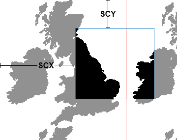
When a background is defined, its map and tile data interact to produce the graphical display:
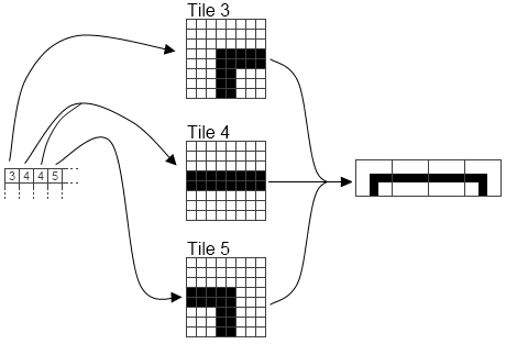
The background map is, as previously mentioned, 32x32 tiles; this comes to 256 by 256 pixels. The display of the GameBoy is 160x144 pixels, so there's scope for the background to be moved relative to the screeen. The GPU achieves this by defining a point in the background that corresponds to the top-left of the screen: by moving this point between frames, the background is made to scroll on the screen. For this reason, the definition of the top-left corner is held by two GPU registers: Scroll X and Scroll Y.
Palettes
The GameBoy is often described as a monochrome machine, capable of displaying only black and white. This isn't quite true: the GameBoy can also handle light and dark grey, for a total of four colours. Representing one of these four colours in the tile data takes two bits, so each tile in the tile data set is held in (8x8x2) bits, or 16 bytes.
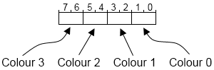
One additional complication for the GameBoy background is that a palette is intersticed between the tile data and the final display: each of the four possible values for a tile pixel can correspond to any of the four colours. This is used mainly to allow easy colour changes for the tile set; if, for example, a set of tiles is held corresponding to the English alphabet, an inverse-video version can be built by changing the palette, instead of taking up another part of the tile set. The four palette entries are all updated at once, by changing the value of the Background Palette GPU register; the colour references used, and the structure of the register, are shown below.
| Value | Pixel | Emulated colour |
|---|---|---|
| 0 | Off | [255, 255, 255] |
| 1 | 33% on | [192, 192, 192] |
| 2 | 66% on | [96, 96, 96] |
| 3 | On | [0, 0, 0] |
Implementation: tile data
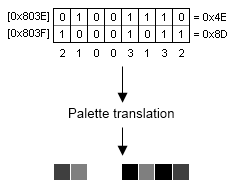
As stated above, each pixel in the tile data set is represented by two bits: these bits are read by the GPU when the tile is referenced in the map, run through the palette and pushed to screen. The hardware of the GPU is wired such that one whole row of the tile is accessible at the same time, and the pixels are cycled through by running up the bits. The only issue with this is that one row of the tile is two bytes: from this results the slightly convoluted scheme for storage of the bits, where each pixel's low bit is held in one byte, and the high bit in the other byte.
Since JavaScript isn't ideally suited for manipulating bitmap structures quickly, the most time-efficient way of handling the tile data set is to maintain an internal data set alongside the video memory, with a more expanded view where each pixel's value has been pre-calculated. In order for this to accurately reflect the tile data set, any writes to the video RAM must trigger the function to update the GPU's internal tile data.
GPU.js: Internal tile data
    _tileset: [],

    reset: function()
    {
        // In addition to previous reset code:
	GPU._tileset = [];
	for(var i = 0; i < 384; i++)
	{
	    GPU._tileset[i] = [];
	    for(var j = 0; j < 8; j++)
	    {
	        GPU._tileset[i][j] = [0,0,0,0,0,0,0,0];
	    }
	}
    },

    // Takes a value written to VRAM, and updates the
    // internal tile data set
    updatetile: function(addr, val)
    {
        // Get the "base address" for this tile row
	addr &= 0x1FFE;

	// Work out which tile and row was updated
	var tile = (addr >> 4) & 511;
	var y = (addr >> 1) & 7;

	var sx;
	for(var x = 0; x < 8; x++)
	{
	    // Find bit index for this pixel
	    sx = 1 << (7-x);

	    // Update tile set
	    GPU._tileset[tile][y][x] =
	        ((GPU._vram[addr] & sx)   ? 1 : 0) +
	        ((GPU._vram[addr+1] & sx) ? 2 : 0);
	}
    }
MMU.js: Tile update trigger
    wb: function(addr, val)
    {
        switch(addr & 0xF000)
	{
            // Only the VRAM case is shown:
	    case 0x8000:
	    case 0x9000:
		GPU._vram[addr & 0x1FFF] = val;
		GPU.updatetile(addr, val);
		break;
	}
    }
Implementation: Scan rendering
With these pieces in place, it's possible to begin rendering the GameBoy screen. Since this is being done on a line-by-line basis, the renderscan function referred to in Part 3 must, before it renders a scanline, work out where it is on the screen. This involves calculating the X and Y coordinates of the position in the background map, using the scroll registers and the current scanline counter. Once this has been determined, the scan renderer can advance through each tile in that row of the map, pulling in new tile data as it encounters each tile.
GPU.js: Scan rendering
    renderscan: function()
    {
	// VRAM offset for the tile map
	var mapoffs = GPU._bgmap ? 0x1C00 : 0x1800;

	// Which line of tiles to use in the map
	mapoffs += ((GPU._line + GPU._scy) & 255) >> 3;

	// Which tile to start with in the map line
	var lineoffs = (GPU._scx >> 3);

	// Which line of pixels to use in the tiles
	var y = (GPU._line + GPU._scy) & 7;

	// Where in the tileline to start
	var x = GPU._scx & 7;

        // Where to render on the canvas
	var canvasoffs = GPU._line * 160 * 4;

	// Read tile index from the background map
	var colour;
	var tile = GPU._vram[mapoffs + lineoffs];

	// If the tile data set in use is #1, the
	// indices are signed; calculate a real tile offset
	if(GPU._bgtile == 1 && tile < 128) tile += 256;

	for(var i = 0; i < 160; i++)
	{
	    // Re-map the tile pixel through the palette
	    colour = GPU._pal[GPU._tileset[tile][y][x]];

	    // Plot the pixel to canvas
	    GPU._scrn.data[canvasoffs+0] = colour[0];
	    GPU._scrn.data[canvasoffs+1] = colour[1];
	    GPU._scrn.data[canvasoffs+2] = colour[2];
	    GPU._scrn.data[canvasoffs+3] = colour[3];
	    canvasoffs += 4;

	    // When this tile ends, read another
	    x++;
	    if(x == 8)
	    {
		x = 0;
		lineoffs = (lineoffs + 1) & 31;
		tile = GPU._vram[mapoffs + lineoffs];
		if(GPU._bgtile == 1 && tile < 128) tile += 256;
	    }
	}
    }
Next steps: Output
With a CPU, memory handling and a graphics subsystem, the emulator is nearly capable of producing output. In part 5, I'll be looking at what's required to get the system from a disparate set of module files to a coherent whole, capable of loading and running a simple ROM file: tying the graphics registers to the MMU, and a simple interface to control the running of the emulation.
Imran Nazar <tf@imrannazar.com>, Aug 2010.