Back to GameBoy Emulation in JavaScript
This is part 3 of an article series on emulation development in JavaScript; ten parts are currently available, and others are expected to follow.
The emulator described in this series is available in source form: https://github.com/Two9A/jsGB
In the previous parts of this series, a structure for a GameBoy emulator was laid out, and brought to the point where a game ROM could be loaded, and stepped through by the emulated CPU. With the emulated processor attached to a memory mapping structure, it's now possible to attach peripherals to the system. One of the primary peripherals used by the GameBoy, and by any games console, is the graphics processor (GPU): it's the primary method of output for the console, and much of the processor's work goes on generating graphics for the GPU.
Emulating the screen
Nintendo's internal name for the GameBoy is "Dot Matrix Game"; its display is a pixel LCD of dimensions 160x144. If each pixel in the LCD is treated as a pixel in a HTML5 <canvas>, a direct mapping can be made to a canvas of width 160 and height 144. In order to directly address each pixel in the LCD, the contents of the canvas can be manipulated as a "framebuffer": a single block of memory containing the entirety of the canvas, as a series of 4-byte RGBA values.
index.html: Canvas tag
<canvas id="screen" width="160" height="144"></canvas>
GPU.js: Canvas initialisation
GPU = {
    _canvas: {},
    _scrn: {},

    reset: function()
    {
        var c = document.getElementById('screen');
	if(c && c.getContext)
	{
	    GPU._canvas = c.getContext('2d');
	    if(GPU._canvas)
	    {
		if(GPU._canvas.createImageData)
		    GPU._scrn = GPU._canvas.createImageData(160, 144);

		else if(GPU._canvas.getImageData)
		    GPU._scrn = GPU._canvas.getImageData(0,0, 160,144);

		else
		    GPU._scrn = {
		        'width': 160,
			'height': 144,
			'data': new Array(160*144*4)
		    };

		// Initialise canvas to white
		for(var i=0; i<160*144*4; i++)
		    GPU._scrn.data[i] = 255;

		GPU._canvas.putImageData(GPU._scrn, 0, 0);
	    }
	}
    }
}
Once a block of memory has been allocated for the screen data, an individual pixel's colour can be set by writing RGBA components to the four values at that pixel position in the block; the pixel position can be determined by the formula y * 160 + x.
Raster graphics
With a canvas in place to receive the graphic output of the GameBoy, the next step is to emulate the production of graphics. The original GameBoy hardware simulates a cathode-ray tube (CRT) in its timings: in a CRT, the screen is scanned in rows by an electron beam, and the scanning process returns to the top of the screen after the end of scanning.
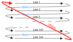
As can be seen above, a CRT requires more time to draw a scanline than simply running over the pixels in question: a "horizontal blanking" period is needed, for the beam to move from the end of one line to the start of the next. Similarly, the end of each frame means a "vertical blanking" period, while the beam travels back to the top-left corner. Since the beam has to move further in vertical blanking, this time period is commonly much longer than the horizontal blanking time.
In the same way, a GameBoy display exhibits horizontal and vertical blanking periods. In addition, time spent within the scanline itself is separated into two parts: the GPU flips between accessing video memory, and accessing sprite attribute memory, while it draws the scanline. For the purpose of this emulation, these two parts are distinct, and follow each other. The following table states how long the GPU stays in each period, in terms of the CPU's T-clock which runs at 4194304 Hz.
| Period | GPU mode number | Time spent (clocks) |
|---|---|---|
| Scanline (accessing OAM) | 2 | 80 |
| Scanline (accessing VRAM) | 3 | 172 |
| Horizontal blank | 0 | 204 |
| One line (scan and blank) | 456 | |
| Vertical blank | 1 | 4560 (10 lines) |
| Full frame (scans and vblank) | 70224 |
In order to maintain these timings relative to the emulated CPU, a timing update function must exist, which gets called after the execution of every instruction. This can be done from an expanded version of the CPU dispatch process, covered in part 1.
Z80.js: Dispatcher
while(true)
{
    Z80._map[MMU.rb(Z80._r.pc++)]();
    Z80._r.pc &= 65535;
    Z80._clock.m += Z80._r.m;
    Z80._clock.t += Z80._r.t;

    GPU.step();
}
GPU.js: Clock step
    _mode: 0,
    _modeclock: 0,
    _line: 0,

    step: function()
    {
        GPU._modeclock += Z80._r.t;

	switch(GPU._mode)
	{
	    // OAM read mode, scanline active
	    case 2:
	        if(GPU._modeclock >= 80)
		{
		    // Enter scanline mode 3
		    GPU._modeclock = 0;
		    GPU._mode = 3;
		}
		break;

	    // VRAM read mode, scanline active
	    // Treat end of mode 3 as end of scanline
	    case 3:
	        if(GPU._modeclock >= 172)
		{
		    // Enter hblank
		    GPU._modeclock = 0;
		    GPU._mode = 0;

		    // Write a scanline to the framebuffer
		    GPU.renderscan();
		}
		break;

	    // Hblank
	    // After the last hblank, push the screen data to canvas
	    case 0:
	        if(GPU._modeclock >= 204)
		{
		    GPU._modeclock = 0;
		    GPU._line++;

		    if(GPU._line == 143)
		    {
		        // Enter vblank
			GPU._mode = 1;
			GPU._canvas.putImageData(GPU._scrn, 0, 0);
		    }
		    else
		    {
		    	GPU._mode = 2;
		    }
		}
		break;

	    // Vblank (10 lines)
	    case 1:
	        if(GPU._modeclock >= 456)
		{
		    GPU._modeclock = 0;
		    GPU._line++;

		    if(GPU._line > 153)
		    {
		        // Restart scanning modes
			GPU._mode = 2;
			GPU._line = 0;
		    }
		}
		break;
	}
    }
Next time: backgrounds and palettes
In the above code, the timings for the GPU are established, but the work of the GPU isn't yet in place: renderscan is where the work happens. In the next part of this series, the concepts behind the GameBoy's background graphics system will be looked at, and code will be put inside the rendering function to emulate them.
Imran Nazar <tf@imrannazar.com>, Aug 2010.