UPDATE: Nov 2021
Petter Källström emailed me, saying that there are a couple of weirdnesses and inefficiencies in the implementation given at the bottom of this article, and provided alternative code as follows:
Petter's more better implementation
-- input = r18, C and H flag-- output = r18 and C flagDAA: push r19 in r19, SREG; Let r19 contain the SREGcpi r18, $9A; Set C flag in r19 if r18 >= 9A, and H flag in SREG if lower nibble is < 10brlo DAA_endif sbr r19, (1<<SREG_C) DAA_endif: sbrs r19, SREG_H; If input H flag was set, then skip the H-flag testbrhs DAA_hi; If H indicate lower nibble is < 10, then jump over...subi r18, -$06; adjust (adjust if r19.H-flag set, or if lower nibble >= 10)DAA_hi: sbrc r19, SREG_C; If output C=1subi r18, -$60; ...adjustout SREG, r19 pop r19 ret
Back to our previously scheduled article:
The Atmel AVR series of microcontrollers can be used in a wide variety of applications, from radios right through to inkjet printers, but a popular application in hobbyist projects is for digital clocks and counters. There are two main portions to any clock or counter program: a piece of code to increment the internal counter, and another piece of code to format and output the counter on a display.
A problem arises where these two portions of code need to interact. If one of these tasks is made less taxing for the microcontroller, the other is made more complicated; as a result, there are two prevailing schools of thought on how to achieve this interaction.
- Easier to calculate: A simple binary number can be held by the controller, which is very easy to increment. This forces the display code to iteratively divide the number down by ten, in order to extract the digits for display.
- Easier to display: A packed binary-coded decimal (BCD) number can be used instead to hold the counter; this simplifies the display logic, but incrementing the number requires an adjustment process to be run in order to correctly align the BCD segments.
This article will examine the implications of choosing the second method: the use of a BCD number to hold the counter.
Packed BCD digits
The concept behind BCD is a simple one: instead of using a byte to represent any value between 0 and 255, a byte is used to represent the decimal digits only: 0 to 9. This allows for each segment of a multiple-digit display to be tied directly to a byte in the number to show, which greatly simplifies the logic behind showing the number.
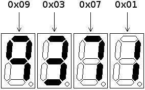
The disadvantage of using a full byte to represent each digit is the waste produced: over 95% of the usable range of numbers in a byte is lost, and a large number of bytes have to be stored for a number of significant size. In a microcontroller environment, where memory space is often at such a premium that one extra byte is significant, this wastage is simply untenable.
An alternative scheme is to use each nybble of a byte to store a BCD digit: in this manner, two digits can be stored inside a byte, increasing the range of values available for storage ten-fold. The code required to pull out digits for display is still very straightforward, since simple boolean operations will yield the required result.
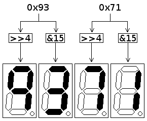
A packed BCD number can be held in half the space of the equivalent full-BCD value, and is a viable compromise between the full range of binary numbers and the ease of display of full-BCD. In addition to this, packed BCD (hereafter referred to as simply "BCD") can be trivially conceptualised, through conversion to hexadecimal: as an example, the BCD value 0x93 represents decimal 93.
BCD addition: the problem
Using BCD to display a decimal number may simplify the display logic a great deal compared to the alternative, but a problem arises when calculations need to be done on the numbers. A microcontroller, much like any other computer of the modern age, is a binary machine with a binary arithmetic unit: it has no understanding of BCD, and will dutifully treat each number coming into it as a plain binary number.
Example additions of BCD numbers
0x15 + 0x03 = 0x18
0x72 + 0x07 = 0x79
0x38 + 0x02 = 0x3A
It is in additions that cause a carry between digits that the problem appears. In the above example, the BCD numbers 0x38 and 0x02 should add to 0x40, but the addition has operated instead on the plain numbers and produced the wrong answer. What is required is a method of adjusting the value after addition, to account for the fact that the values being operated on are BCD.
The Intel IA-32 series of microprocessors contains such a method as part of the base instruction set: Decimal Adjust after Addition (DAA). If this instruction is run after an addition, the result stored in the accumulator will be adjusted.
DAA usage on Intel x86
mov al, 38h add al, 03h; At this point, al = 0x3Bdaa; al = 0x41
The Atmel AVR doesn't contain such a convenient instruction as DAA, but the algorithm behind the DAA instruction is documented as part of the Intel IA-32 Reference manual, and is simple both to understand and to re-implement.
The decimal adjustment algorithm
DAA will adjust a BCD value that has had a carry occur between digits. There are two situations where this applies:
- BCD carry: This occurs in a situation much like the one detailed above, where a result is too large to fit into a BCD digit but is still large enough for a binary nybble. Checking for this is simple: if the nybble has a value over 9, BCD carry has occurred.
- Binary carry: This will happen if a BCD digit addition result is not just larger than a BCD digit, but larger than 15: the nybble containing the BCD digit will itself carry, and end up with a value lower than 9. Results of this type would not be caught by the check for values over 9.
Most processor architectures maintain a status flag denoting when a byte has carried past its maximum value; many architectures also maintain a half-carry flag, that is set when the lower nybble of a byte carries into the upper nybble. The half-carry flag will be set by a BCD addition that causes a binary carry in the lower digit, so checking for this will satisfy the other half of the DAA check.
If the DAA check finds a digit that needs adjusting, the fix is simple: a further addition onto the nybble in question.
Adjustment of a nybble
0x08 + 0x03 = 0x0B; Should be 0x110x09 + 0x05 = 0x0E; Should be 0x140x09 + 0x08 = 0x11; Should be 0x17
In every case, the value is six away from where it should be, so the adjustment adds six to bring the value back into BCD. Applying this process to both nybbles yields the final DAA algorithm.
2-digit BCD decimal adjustment after addition
OLD_value = Value OLD_carry = Carry from addition# Check lower nybbleIF (Half-carry set by addition) OR (Lower nybble of Value > 9) ADD 6 to Value FI# Check upper nybble # Upper nybble will be over 9 if original Value was over 0x99IF(OLD_carry) OR (OLD_value > 0x99) ADD 0x60 to Value Carry = 1# BCD value carry occurredELSE Carry = 0 FI
The DAA algoithm sets the carry flag based on whether the upper nybble overflowed; this allows DAA to be used on BCD values across multiple bytes, by employing addition-with-carry on any higher denominations.
Implementing DAA on AVR
Translating DAA from the algorithm detailed above results in the following AVR code.
AVR implementation of DAA
; Parameters: R16 = value to adjust ; Returns: R16 = Adjusted value ; Carry flag set if adjustment caused BCD carryDAA: push r16 push r17 push r18 push r19 push r16 mov r17, r16 mov r18, r16 in r19, SREG andi r19, (1<<SREG_C) clc brhs DAA_adjlo andi r17, 0x0F cpi r17, 10 brlo DAA_hi DAA_adjlo: ldi r17, 6 add r16, r17 DAA_hi: tst r19 brne DAA_adjhi pop r17 cpi r17, 0x9A brlo DAA_nadjhi DAA_adjhi: ldi r17, 0x60 add r16, r17 sec rjmp DAA_end DAA_nadjhi: clc DAA_end: pop r19 pop r18 pop r17 pop r16 ret
Usage of the DAA routine for a two-byte BCD value stored in SRAM, would work like this:
Calling DAA across two BCD bytes
; Add BCD 57 to the value stored at SRAM:0x100ldi xl, 0x00 ldi xh, 0x01; Read in low byte, add 57 BCD, and storeld r16, x ldi r17, 0x57 add r16, r17 call DAA st x+, r16; Read in high byte, add carry from low byte, and storeld r16, x clr r17 adc r16, r17 call DAA st x, r16
Other decimal adjustment routines
The Intel IA-32 instruction set also contains a routine for decimal adjustment after subtraction, which operates in a slightly different manner to that detailed above. Development of such a routine for AVR is beyond the scope of this article, but can be done in a similar vein to DAA by pulling the algorithm from the IA-32 Reference manual.
If this routine proves useful, or if you come across any bugs with its operation, please feel free to let me know.
Imran Nazar <tf@imrannazar.com>, Dec 2009. Code released into the public domain.