Time for a look at the Commodore 64, and its 1541 disk drive: why was it so dang slow? Let's take a look at the history leading up to the C64's release, and the technical detail of the disk drive's operation.

The Commodore 64 is, of course, the greatest computer ever made, and you don't have to take my word for that: it still holds the world record for highest number of units of a single model of home computer ever to be sold. Estimates vary, but at the high end there were 17 million C64's out there.
Commodore holds another, more dubious record from around this time though. The 1541 disk drive that was sold alongside the C64 is infamous for its slow load speed: benchmarks across systems are hard to find, but it might be the slowest disk drive ever sold to the general public.
Brandon Staggs has a benchmarking tool he's written for the C64[1]CBM Disk Transfer Benchmark, Brandon Staggs, which measures load speeds for the 1541 and its modified brethren, and he's found that the unmodified 1541 as sold at launch was capable of reading files in at around 400 bytes per second:

For comparison, the Commodore 64's tape drive could load files at ~100 bytes per second (though the operating system loaded files from tape twice, to correct for errors); the disk drive isn't much faster than the tape deck, which is equivalent to shouting programs into the computer.
So how did Commodore Business Machines get to the point where its disk drive was the slowest on the market, making its flagship machine essentially useless for business purposes? Unsurprisingly, it wasn't intentional. Let's go back in time a few more years, to Commodore's first computer.
The Commodore PET and the IEEE-488 interface
In 1976, Chuck Peddle was working at Metal Oxide Semiconductor who made calculator chips, and had just started making the 6502 microprocessor. He got to talking with Jack Tramiel at Commodore, and was tasked with procuring or designing a machine for the 1977 Consumer Electronics Show.

Initial discussions with Steve Jobs to buy the Apple II design fell through after Tramiel thought Jobs was charging too much. (Can you imagine an Apple II sold by Commodore? We'd be in a very different world if that had happened...)
So Peddle put together a machine based on his demonstration board for the 6502, and a working prototype was ready in time for the CES in January. It was called the Pet Computer, after a Commodore executive saw the Pet Rock and suggested jumping in on that trend while it was still hot.

The Personal Electronic Transactor, as the backronym eventually came about, came with an IEEE-standard parallel port interface; Commodore's first disk drives (the 2020 and 2040) could read files in at over 2kB per second, which was a perfectly serviceable speed for the time.

(As an aside, the version of BASIC that came with the first PET had no disk handling commands: the code for talking to the parallel-port bus was broken on release, but Commodore's kernel was able to work with disk drives, so you had to write your own file handling routines.)
(As another aside, Commodore didn't pay Microsoft for BASIC until the PET shipped, and it was delayed by almost a year; Microsoft were only saved from bankruptcy when Apple bought BASIC for the II. Another inflection point in history, and we're barely 10% of the way in.)
So the PET and its 2040 drive were Fine, but they had one problem: that IEEE-488 interface. As it turned out, there was exactly one manufacturer of the cables you needed to connect your computer to your disk drive: Belden Cables of Chicago.

And it wasn't so much that Belden went out of business, more like they vanished off the face of the earth. As Jim Butterfield put it in his Brief History of the IEC Bus[2]"A Brief History of the IEC Bus" by Jim Butterfield, as compiled by Jan Derogee, Feb 2008:
A couple of years into Commodore's computer career, Belden went out of stock on such cables (military contract? who knows?)
Now, Commodore had stock of these disk cables on hand for its existing business computers, but there was no way they'd have enough for Tramiel's intended move into the home computer market which was just coming into being.
Not only that: the parallel ports, the cables, the wiring, every part of the IEEE-488 interface was expensive. The PET started at $500 in 1977 dollars, but that got you 4KB of RAM and a mono screen; a usable spec would set you back over a thousand.
Jack Tramiel wanted to sell a computer with colour graphics into the home market for $300. The only way to get there would be to cut every corner going, and one of the most obvious was that huge interface with over twenty wires running to it.
And so, to take another excerpt from Butterfield, the order came to Commodore's engineers from on high:
Tramiel issued the order: "On our next computer, get off that bus. Make it a cable anyone can manufacture". And so, starting with the VIC-20 the serial bus was born.
A "new" serial interface
Why is a serial bus cheaper? With a parallel bus, you need at least nine wires to run 8-bit values back and forth: the full value is set on the eight Data lines, and then you pulse the Clock line to tell the other side that a value is ready. Add in Power and Ground, you're at 11 wires already.

A serial bus works one bit at a time: you have one Data line, place a bit on there, and pulse Clock to tell the other side the bit is ready. Then you send the next bit, and the third... Because all the bits have to line up and wait to be sent, it takes at least 8 times longer to send a value.
But you'll notice there's only one Data line and one Clock. Add in Power and Ground, and you're up to four. You might recognise this actually, if you look at a Universal Serial Bus (USB) cable: the end has four pins, and clocking works differently for USB but the same principle applies.

So a serial bus cable is a lot cheaper, and a serial interface on your computer's mainboard is cheaper as well, than a parallel setup. It's eight times slower to send a value, but you can make up for that by running the interface at eight times the previous speed, if you have the hardware.
And while he was at MOS, Chuck Peddle had put something very nifty into the PET's Versatile Interface Adapter chip (model number 6522) which was used to drive the parallel bus: a shift register.

A shift register is a piece of hardware that lets you very quickly push consecutive bits out of a given wire: you can queue up a full value of 8 bits, and with each pulse of the Clock the register will push the bit at the end out, and 'shift' all the others down one step.
Conversely, you can have a shift register that listens for bits on a wire, and shifts the value up a step with each clock pulse, building a full value as it goes. Put two of them either side of a serial bus, and you have yourself most of the hardware for high-speed data transfer.
The only thing you'd need aside from these shift registers is a line for the machines to tell each other they'd pulled in the byte and were ready for another: Commodore were thinking a fifth wire would be useful for this.
Crucially, the CPU isn't involved at any point until the full byte is ready: this interface runs itself until it has a full value, then signals the CPU to collect it and heads off to build another byte. That means a 1MHz machine could push data at a blistering 10kB/sec or even more.

The theory was sound, and Commodore's engineers got to work building the VIC-20 (named after its custom Video Interface Chip) heading for that magical price point of $300 for the home market. There was just one problem...
The shift register bug
To quote Butterfield again:
We early PET/CBM freaks knew, from playing music, that there was something wrong with the 6522's shift register: it interfered with other functions.
With a speaker attached to the shift register wire, you could play music on the PET, but sometimes it ...got stuck.
The PET ran on the order of 1MHz, so instructions took microseconds to execute. The 6522's shift register as implemented in hardware had a bug, where if the register line changed within a few _nanoseconds_ of Clock changing, it would go to full voltage and stick until the computer was reset.

NO SHIFT WILL OCCUR IF CB1 RISING EDGE IS WITHIN THE SHADED AREA. Credit: 6502 Archive, via the Internet ArchiveThis was a timing bug many times more subtle than the main clock, so it's no surprise that no-one caught it until people started playing with the PET's internals. Importantly, no-one at Commodore knew this bug existed when they designed the VIC-20's serial bus around the 6522.
The bug was discovered with only a couple of months left to release of the VIC-20, and the boards were already in manufacturing. This problem couldn't be fixed in hardware: the engineers would have to "do it in post", which in the computing world means in software.
Instead of having the CPU get pinged when each byte was ready, it would have to camp on the serial bus's input itself and listen for changes in the Clock signal, pulling each bit in as it arrived and signalling to the other end that it was ready to receive the next bit.
Of course, this would mean the 1540 disk drive, which was being released alongside the VIC-20 computer, would also need its software changing: it used the exact same setup of a CPU with a 6522 attached, and it had the same bug, so it would be pushing bits out only when the computer said so.

In the end, emulating the shift registers in software meant the VIC-20 serial bus could only run at a relatively sedate 1kB/sec, and chewed up all the CPU on the machine to do it. Fortunately there were two things about the VIC-20's design that meant this wasn't so bad.
The first was its measly offering in terms of memory: targeted for the home market, the VIC-20 came with 5kB of RAM to play with. Would you notice if it took 5s to load a file from disk instead of half a second? And what would you do with a memory full of file and no room to work on it?
The second was the clever design of the VIC-20's main clock: running at 1MHz, the CPU would kick in when the clock went up, and the video chip worked when the clock went down. Interleaving in this way, both chips could access memory without stepping on each other, both at full speed.

All this put together meant that you could use a VIC-20 with the 1540 perfectly serviceably: loading a file didn't blank out the screen or anything weird, and it was over in a couple of seconds. The serial bus had done its job, and helped the machine hit that $300 price point.
There's a short tale on the Greater Pittsburgh Vintage Computer Museum at https://www.myoldcomputers.com about the VIC-20, but take a moment to revel in the 90s design of that website: the navigation buttons, the tables with the borders... A simpler time.

Anyway, story goes that Tramiel sold the VIC-20 in Japan, and its price so shocked other manufacturers that they delayed entering the American market to work out how it was possible. We never saw Toshiba or Panasonic 8-bits outside Japan because they were locked out by that delay.
After the VIC-20
The VIC-20 ended up selling like hot cakes, becoming the first model of computer to sell more than a million units. The most surprising part to Commodore was people who bought the machine solely to play games: productivity and business software sold poorly in comparison.
And so in 1981, Commodore's Japan subsidiary began designing the Ultimax console[3]Tale of the Ultimax, Greater Pittsburgh Vintage Computer Museum, and dragged their partners at MOS into designing a successor to the VIC chip as well as a more advanced sound interface, aiming for an eventual price point of $200.

By the start of the next year, the Ultimax was ready, but it had a problem: several problems, in fact. At such a low price, the keyboard was atrocious; it shipped with 2kB of RAM; there was no inbuilt tape-reading software, so each game had to implement its own, and only two games did.
The Ultimax's biggest problem, though, was the VIC-20: still selling fantastically, it was now regularly discounted to $200, and was a much more capable machine. There's a reason the Ultimax is known as a very rare machine nowadays: Commodore didn't sell many.
Back in the US, Tramiel was turning his focus back to the business market with new models of PET, but the engineers at MOS thought they had something very capable on their hands that didn't deserve an undignified death in the Ultimax: they proposed a sequel to the VIC-20 for the home market.
Tramiel agreed to kick off the project (codename VIC-40) but only if it came with 64kB of RAM to make for a more usable computer. The engineers were given two months to turn a machine around in time for CES 1982, and by recycling all of the Ultimax's innards they made it in the nick of time.

It wasn't called the VIC-40 at CES, of course: it was the Commodore 64. We made it to the machine we actually want to talk about, and it only took 47 posts. If you've slogged through this far, we're almost on the downhill stretch.
While the C64 was being designed, the engineers at MOS had been hard at work fixing the shift register bug in the 6522. The '64 had an upgraded version of the adapter chip: the 6526 Complex Interface Adapter, with the kinks worked out.
Back in Commodore Engineering, the team knew from experience with the VIC-20 that they had a very short window to get the hardware design right for the C64, and more time for software, so they devised a clever scheme to keep their options open regarding the 6526's shift register:
To keep backwards compatibility with the VIC-20's disk drive, the C64 could boot up in a slow-serial-bus mode where the data line was camped on by the CPU in its usual fashion. But the bus's data signals could also go to the 6526, by running a branch off the data line on the mainboard.
If they got the software right, the user could switch into fast-serial-bus mode and the CIA's shift register would do its job talking to a corresponding faster disk drive (which would also have a 6526 on board). The idea was elegant, but Murphy's Law would get in the way.
The hardware design was finalised and sent off to be built. David Callan picks up the story[5]David Callan's reply to a Lemon64 forum thread: "Trying to understand why is 1541 so slow", Jun 2014:
A minor rework of the board at the board manufacturers (to accommodate a screw hole, I believe) accidentally discarded the high-speed wire.

Cutting through the fast-serial-bus line doomed the C64 to the same slow data transfer speeds as the VIC-20: around 1kB per second. The boards were already designed around the 6526's layout, but they would be left in VIC-20 compatibility mode.
But we don't see the 1kB/s achieved by the VIC-20 when measuring the disk loading speed on a real C64: we actually get less than half that. So what's going on to make the C64 slower? Now bear with me, we're going to get technical. (Yep, we haven't been technical thus far.)
We're going to take a little bit of a detour from talking about disk drives and interface adapters, and look at the history of television real quick. Stay with me, we'll get back on track very shortly. If you're already familiar with TV signals, come back in fifteen posts or so.
What is a television, and what does it do?
The first TV broadcast systems took a two-dimensional picture that varied with time, and crammed that information into a one-dimensional radio signal: kinda like a sound wave, all you had was a volume (or amplitude) that went up and down with time.
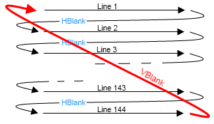
So how do you turn 2D frames of video into 1D? By breaking them up into lines, and sending the lines one after another. If you used enough lines, you could send a full picture without things looking janky; if you then sent a frame very quickly after the first, you had the illusion of motion.
In the US, things eventually coalesced around a 525-line standard, but if you wanted to send 525 lines of picture at 60 frames per second there wasn't a way to fit that much signal into the allocated radio bands. The ingenious solution was to send half the picture at a time.

The transmitter actually takes 60 frames of video per second, but it sends every other line from one frame and the lines it missed from the next frame; at the receiving end, the eye and brain blur things together and it looks like the whole frame is moving at full speed.
So let's have a quick look at one of these lines, as it comes in from the VHF antenna. If we want to show bands fading between white and black across the screen, that's represented by a signal that starts high (for white) and drops to low (for black), then back up.


But what's this "Horizontal Blanking Period" that shows up after the picture data? To understand why that appears, we need to look at the television technology of the time: the cathode ray tube.
The CRT is actually a 19th-century invention: the story starts with Julius Plücker playing around with sealed glass tubes containing various gases. By putting a wire at each end, Plücker found he could get a current to run through the tube, and some gases would glow under current.
(As an aside, the Plücker tube is nowadays called the Geissler tube, and types of Geissler tube include neon signs and the sodium lamps you find in streetlights.)
In 1859, Plücker noticed that the wall of the tube was itself glowing near the cathode end of the electric flow, and he could get the glow to move around by applying an electromagnet to the outside. There was something about the cathode that was causing the glass to phosphoresce...
Cathodoluminescence, as it came to be known, was neatly explained by Einstein as a side-effect of his exploration of the photoelectric effect in 1905. If we take the photoelectric effect first, that occurs when light falls on a surface of a particular material, ejecting electrons.

The opposite of this is when electrons are fired at a substance and it starts to emit light. A mix of zinc cadmium sulfide and zinc silver sulfide will output white light when struck by electrons, and it's this mix that coats the inside of a monochrome display CRT.

By combining cathodoluminescence and Plücker's insight that the cathode ray can be deflected with magnets, we can program a CRT to scan across the screen and produce a picture: white areas are activated with more power from the cathode, black areas with less power.
The beam can be deflected from left to right by applying more magnetic field strength to one side or the other, gradually fading from one magnetic coil to the other. But what happens when we reach the right edge, and want to come back to the left?
Magnetically it's simple: drop the power on the right deflection coil to nothing, and turn the left to full. But the beam doesn't simply blink out of existence and reappear on the left: it takes time for the magnetic field to dissipate.
And that's why television signals have a blanking period: to provide time for the magnets in the CRT to flip polarity and bring the beam across to the left for the next scan. As well as horizontal blanking, there's a vertical blanking period to allow for travel back to the top for the next run.
Interleaved memory access
So why do we care about the architecture of TV signals when we're dealing with computers? Because they have to have somewhere to output their video, and it makes sense for computers destined for the home to output onto the TVs that people already had in their homes.
We've looked at _how_ video comes out of the computer onto a TV, let's have a look at _what_ is displayed. On the VIC-20, the default video mode is tiled, or character mode: 23 rows of 22 characters, with each character being 8x8 pixels, for a resolution of 176x184.

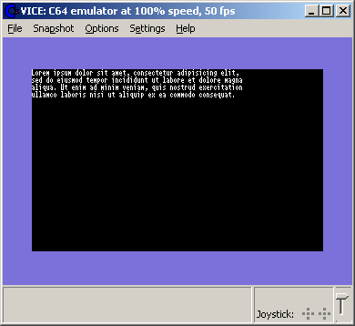
**** CBM BASIC V2 ****
3583 BYTES FREE
READY.
To get a character rendered on the screen, the VIC chip needs data from three places: which character to show, its colour, and information about its shape. Each of these uses a region of memory on the VIC-20: screen RAM, colour RAM, and the built-in character generator ROM.

You'll recall from earlier that we talked about how the VIC-20 interleaves its CPU and video clocks, allowing the video chip to access memory at the same time as the CPU. At 22 characters across, it takes 44 cycles of the clock to pull in what the VIC needs to draw a given line.
"But wait", I hear perhaps a few of you cry. If we need three pieces of data to render a character, that should be 66 cycles of memory access; what magic allows each character to be rendered in two memory reads instead of three? Once again, we turn to the magicians at MOS.
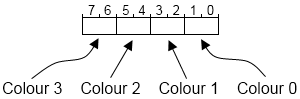
The VIC has 16 colours: every unique combination can be expressed in four bits. Colour RAM on the VIC-20 isn't the normal eight-bit memory of the rest of the machine, it's four-bit RAM, and the VIC chip itself has a combined 12-bit data bus to read from both types of memory at once[6]How the VIC20 Works, Tynemouth Software:

And finally, we cycle back around to the disk drive. With this interleaving of memory access in the VIC-20, the CPU does its best impression of a shift register, and the VIC has 65 cycles (including the horizontal blanking period) to do 44 memory reads[7]VIC-20 video timings, Jon Brawn; positively relaxed.
The C64 is a different story. We're still in 16 colours, but tiled character mode now yields a screen of 40 characters by 25 rows, for an effective resolution of 320x200; the VIC-II chip would need 80 cycles to get all its data read in, and it only has 65 cycles to play with.
Yet again we call on the wizards at MOS for an ingenious solution, and this one was a doozy. They noticed that it takes around 500μs to draw eight lines (one row of characters) on the screen, and _generally_ users weren't changing the characters in RAM in that short span of time.
The original VIC would read a character number from screen RAM, then head into the character generator ROM to find the line of that character it needed to draw; on the next line, it would do the same steps, but the character number would very likely be the same.
Wouldn't it be neat if we could cache screen RAM somewhere (inside the VIC-II, say) every eight lines, and read from there instead of heading out to memory so many extra times? You could even apply the same logic to colour RAM, since it was read at the same time on that 12-bit bus.
So that's what they did: build a 12-bit cache for the screen and colour RAM values onto the VIC-II silicon, and push everything else around to compensate. The video chip uses this cached copy of the screen to index the character generator ROM and work out which shapes to draw.

There's just one problem. This works great for seven out of eight lines where we already have the screen/colour data cached, but the first line of each row of characters invalidates the cache, and we need to fetch from all three places. We're back to having 65 cycles to do 80 cycles' work.
Fortunately, this problem was found before the hardware was finalised, so there was time for a hack: every eight lines, the VIC signals to the CPU that it's taking over the memory bus, and the CPU isn't allowed to do any work for 40 cycles.

By building an Address Enable Control line into both the VIC and the 6510 CPU, the VIC can steal access to memory by pulling the line from its default state of full voltage down to zero; when this happens, the 6510 puts its memory bus into high-impedance mode, which blocks any usage by the CPU.
Of course, this includes the serial bus's data line, so the CPU is locked out from camping on the serial bus 12.5% of the time during normal computer operation. This is often referred to as a "badline" condition, because the one in eight lines where this happens are the bad lines.
Let's detour real quick into what it means to camp on the data line: what is the CPU actually doing when it spins its wheels waiting for data to come in? To find out, we need to dig into the operating system that was burned into the VIC-20's ROM chips.
Many people have done excellent work disassembling and annotating the VIC-20 ROM, and a complete set has been compiled by Lee Davison; the file is hosted by Matt Dawson here: https://www.mdawson.net/vic20chrome/vic20/docs/kernel_disassembly.txt
If we count up the time taken by the instructions in the relevant section of this disassembly, we find it takes at least 19μs to read in a single bit from the serial bus; with the surrounding code, it can be more like 500μs to read a full byte, before the rest of the OS even sees it:
    LSR                ; serial data into carry
    ROR    LAB_A4      ; shift data bit into receive byte
LAB_EF66
    LDA    LAB_911F    ; get VIA 1 DRA, no handshake
    CMP    LAB_911F    ; compare with self
    BNE    LAB_EF66    ; loop if changing
    LSR                ; serial clock into carry
    BCS    LAB_EF66    ; loop while serial clock high
    DEC    LAB_A5      ; decrement serial bus bit count
If we take this same code and run it on the C64, it's going to miss bits: if it runs through every 19 cycles, but the CPU is occasionally locked out for 40 cycles, you can miss two or even sometimes three bits of data.
Luckily, the serial bus is robust enough to handle this: it will hold a value on the data line until it's told by the other end that the value has been saved. If the CPU is locked out, the data stays there until it comes back from its short coma.
The final solution that Commodore landed on was to delay the C64 end of the serial bus so it sent a bit every 60μs, to be sure it wasn't catching a badline in its own CPU, and to leverage the serial bus's acknowledgement mechanism for any delays in reading data.
All's well that ends well...?
And there we have it: with the change from 19μs/bit to 60μs, we find the effective speed of the C64 and its disk drive comes out to 400 bytes per second. That leaves us with only a couple of questions...
Did this affect sales of the C64? Eh, not really. Being heavily advertised to the home market as a successor to the VIC-20, users were willing to wait a little while for their games to load, and even 400 bytes per second was better than the interminable wait for tapes to load.
And whatever happened to Commodore? Well, Jack Tramiel stepped down after the success of the C64, and he was very much in the mould of Steve Jobs: a driver of high concept. Without Tramiel, Commodore started to pull in multiple directions at once...[8]The downfall of Commodore, Bradford Morgan White
The Plus-4 and 264 home machines with low prices and low specs to match performed badly; a new series of PET-derived 8-bit business computers didn't sell as the IBM PC and its clones started eating the business market; Tramiel went on to head Atari and release the ST line of 16-bits.
Commodore's last gasp effort was to buy Amiga and develop their prototype 16-bit machine into the Amiga 1000, but even that faltered as Commodore demanded it be treated as a Serious Business Machine; it took until 1987 before the A500 was sold as a 16-bit home machine, and profits returned.
But profits didn't rebound by enough for Irving Gould, main investor in Commodore, to be happy; he fired the CEO, laid off half the staff, and directed work back to 8-bit machines. Only one of these ever saw the light of day: a 1991 rework of the C64 in a slimline Amiga-style case.
And then a patent troll sued over the use of mouse cursors in the Amiga, and incredibly, Commodore lost. That was 1993, they refused to pay up, and were banned from selling in the US; Commodore shut their doors in April of 1994, but the C64's sales record stands to this day.
If anyone ever asks you "Why was the C64's disk drive so slow?", now you'll have an answer.
(Postscript: I bought a copy of the C64 Programmer's Reference at a yard sale when I was 12, and called the number on the back from a payphone. I was told that the number didn't go to Commodore any more, and that's how I learned they were no longer a going concern. Devastated.)
]]>


